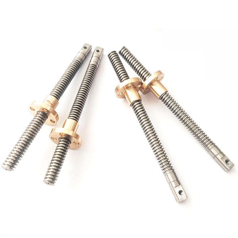
头部背景图片

How to Optimize Heat Dissipation Design for Linear Modules in High and Low Temperature Environments?

2025-12-19

To optimize heat dissipation for Linear modules in high and low temperature environments, a comprehensive approach must be taken across five dimensions: material selection, structural design, heat dissipation methods, temperature control, and environmental adaptability. The specific strategies are as follows:


1、High Thermal Conductivity Materials and Interface Optimization

Core Material Upgrades

Use aluminum nitride (AlN, thermal conductivity ~200 W/m·K) or graphene composite materials as substrates, replacing traditional alumina ceramics to improve thermal conductivity by over 5 times.

Select interface materials such as thermal paste (thermal conductivity ≥3.3 W/m²·K) or thermal gel (≥3 W/m²·K), ensuring the contact area between the module and the heat sink covers at least 70% of the chip area to eliminate air gaps (thermal conductivity of air: ~0.026 W/m·K).

Low-Temperature Environment Adaptation

Use solid-state electrolytic capacitors instead of liquid capacitors to avoid performance degradation at low temperatures. Increase startup capacitor capacity or add parallel MLCCs (multilayer ceramic capacitors) to enhance startup current in low temperatures.

Select wide-temperature-range components (e.g., chips operating from -40°C to 125°C) to prevent performance degradation in low temperatures.


2、Innovative Heat Dissipation Structural Design

Heat Pipe and Vapor Chamber Technology

Heat pipes should adopt a flattened design (thickness ≥1.5 mm), avoiding excessively small bending radii (recommended R ≥ 3 times the heat pipe diameter) to minimize thermal resistance.

Vapor chambers (VCs) use internal conductive textures to expand the heat exchange area, allowing heat from high-temperature areas to be uniformly conducted in vapor form.

Fin and Airflow Optimization

Fins should be oriented in the direction of the fan airflow to reduce wind resistance. The number and height of fins should be adjusted based on power density.

Design independent airflow channels to ensure cold air flows through the core area of the module and hot air is efficiently expelled.


3、Active Heat Dissipation and Intelligent Temperature Control

Multi-Mode Heat Dissipation Systems

Air Cooling: Use axial fans or blower fans (centrifugal blowers) with dynamically adjustable speeds based on temperature.

Liquid Cooling: For high-power Linear modules, adopt a "cold plate + circulation pump" system that uses phase-change fluid cycles to dissipate heat, improving efficiency by over 50% compared to air cooling.

Hybrid Cooling: Combine heat pipes, fins, and fans to achieve efficient heat dissipation.

Intelligent Temperature Control

Embed negative temperature coefficient (NTC) thermistors or digital temperature sensors to monitor chip temperature in real time.

Dynamically adjust loads or heat dissipation strategies based on temperature thresholds.


4、Enhanced Environmental Adaptability

Protection Against Extreme High and Low Temperatures

High Temperatures: Allow sufficient temperature margins for components and select high-temperature-tolerant devices. Use multiple devices in parallel to distribute heat and avoid single-point overheating.

Low Temperatures: Use low-temperature solder to ensure reliable solder joints even below -40°C. Avoid concentrated thermal stress by dispersing heat sources in PCB layouts and reducing mechanical stress damage caused by material expansion and contraction.

Protective Structure and Sealing Design

Module housings should use stainless steel materials with fully sealed structures, achieving electromagnetic shielding effectiveness (SE) of ≥40 dB to withstand strong interference in the 30 MHz–1 GHz frequency range.

Critical interfaces should use waterproof connectors (IP65 rating) and shock-absorbing pads (silicone material) to withstand vibrations of 10–2000 Hz and 10g acceleration, preventing loose connections or chip solder joint detachment.


5、Simulation and Testing Verification

Thermal Simulation Optimization

Use software such as FloTHERM for transient thermal analysis to simulate the thermal distribution of Linear modules at different temperatures and optimize heat dissipation structures.

High and Low-Temperature Aging Tests

Place Linear modules in high-low temperature test chambers and perform cyclic tests from -40°C to 85°C to verify their startup performance, output stability, and lifespan under extreme temperatures.


What are the performance differences between high and low temperature Linear modules and ordinary Linear modules?

2025-12-19

The performance differences between high/low temperature Linear modules (typically referred to as industrial-grade or wide-temperature-range modules) and ordinary Linear modules (typically consumer-grade or commercial-grade modules) stem from their distinct design goals and intended operating environments.

Simply put, high/low temperature Linear modules sacrifice peak performance and power efficiency in exchange for stability, reliability, and long-term lifespan under extreme temperatures.

Below is a detailed comparison across several key dimensions:

1. Operating Temperature Range (The Core Difference)

Ordinary Linear Modules: Typically designed to operate within the commercial temperature range of 0°C to +70°C. This covers the environment for most consumer electronics (e.g., phones, computers, home appliances).

High/Low Temperature Linear Modules: Have a much wider operating temperature range, commonly including:

Industrial Grade: -40°C to +85°C

Automotive Grade: -40°C to +105°C (or even higher, with more stringent requirements)

Military/Aerospace Grade: -55°C to +125°C or wider.

Some specialized Linear modules can even operate in cryogenic environments below -100°C or high-temperature environments above +200°C.

2. Performance Stability and Reliability

Ordinary Linear Modules: Perform to specification within their rated temperature range. Performance can degrade sharply outside this range, potentially leading to timing errors, data loss, or even physical damage (e.g., electrolytic capacitor failure). Their design lifespan is typically a few years.

High/Low Temperature Linear Modules:

Low-Temperature Performance: At extremely low temperatures, carrier mobility in standard semiconductors decreases, reducing performance. These Linear modules employ special circuit design, component screening, and material selection to ensure normal startup and operation.

High-Temperature Performance: At high temperatures, component leakage current increases and heat dissipation becomes difficult, which can lead to thermal runaway. These Linear modules use high-temperature-resistant semiconductor processes, highly stable passive components (e.g., tantalum capacitors, ceramic capacitors), and rigorous thermal design.

Thermal Cycling Endurance: They must withstand repeated shocks from extreme cold to extreme heat, posing a significant challenge to the integrity of solder joints and packaging materials. They undergo strict thermal cycling tests.

3. Component Screening and Manufacturing Process

Ordinary Linear Modules: Use commercial-grade chips and components with standard production processes aimed at reducing cost and increasing yield.

High/Low Temperature Linear Modules:

Chip Level: Use industrial-grade, automotive-grade, or military-grade core chips (e.g., MCUs, memory, power ICs). These chips undergo stricter testing and screening at the wafer production stage to eliminate units with poor performance under extreme temperatures.

Component Level: Use exclusively wide-temperature-range passive components (resistors, capacitors, inductors), connectors, and PCB materials (e.g., high Tg laminates).

Process Level: May employ Conformal Coating for protection against moisture, corrosion, and salt spray. Higher standards for soldering processes are required to prevent cold joints.

4. Peak Performance and Power Consumption

Ordinary Linear Modules: To pursue high performance (high clock speed, high bandwidth, low latency), they often use more advanced manufacturing processes and aggressive power designs, offering the best experience at room temperature.

High/Low Temperature Linear Modules: Often operate at "downclocked" speeds or use more conservative designs.

Advanced processes can suffer from increased leakage current at high temperatures, so sometimes more mature but stable processes are preferred.

To control total power consumption and heat generation at high temperatures, their rated maximum operating frequency (e.g., CPU clock speed) may be lower than that of their consumer-grade counterparts.

In short: At room temperature, an ordinary module of the same technology generation may outperform a high/low temperature module in terms of speed.

5. Cost and Price

Ordinary Linear Modules: Cost-effective, competitively priced.

High/Low Temperature Linear Modules: Highly expensive. Reasons include:

The wide-temperature-range chips and components themselves are costly.

More complex material management and production processes.

Extremely rigorous testing (thermal cycling, extended burn-in, etc.) increases time and capital costs.

Their price can be several times to tens of times higher than that of ordinary Linear modules.

Application Scenario Comparison

Ordinary Linear Modules: Indoor electronics, office equipment, personal consumer electronics, general networking equipment.

High/Low Temperature Linear Modules:

Industrial: Outdoor industrial control, automation equipment (e.g., polar research stations, steel plants), power inspection, oil & gas exploration.

Automotive: Engine Control Units (ECUs), in-vehicle infotainment systems, autonomous driving sensors (mounted outside the vehicle, exposed to heat and cold).

Military/Aerospace: Satellites, missiles, radar, field communication equipment.

Medical: Certain in-vitro diagnostic equipment, low-temperature storage monitoring.

Outdoor: Base stations, surveillance cameras (outdoor models), drones (used for polar or desert research).

Summary Table

 differences between high and low temperature Linear modules and ordinary Linear modules

Conclusion:

The choice of module depends entirely on the application scenario. If your device operates in a climate-controlled indoor environment, ordinary Linear modules offer the best value. If your device needs to be deployed in a desert in summer, the Arctic in winter, a moving vehicle's engine bay, or the harsh environment of space, then high/low temperature Linear modules are fundamental to ensuring system survival and functionality. Their value far exceeds what performance specifications alone can measure.

Advantages of Glass Solid Phase Reactor Combined with a Collection Bottle

2025-12-17

 Advantages of a Glass Solid Phase Reactor with Collection Bottle

In laboratory and pilot-scale chemical processing, solid–liquid reactions often require not only precise reaction control but also efficient solid separation and product collection. A glass solid phase reactor combined with a collection bottle offers an integrated solution that improves process efficiency, cleanliness, and experimental reliability. This article outlines the key advantages of this configuration and explains why it is widely used in chemical and pharmaceutical research.


Integrated Reaction, Filtration, and Collection

A glass solid phase reactor with a collection bottle allows the entire workflow—reaction, solid–liquid separation, and filtrate collection—to be completed within a single system. After the reaction, liquid phases pass through the filter and are collected directly in the bottle below, eliminating the need for additional transfer steps.

Advantage:
Reduced handling, minimized material loss, and improved operational efficiency.


Cleaner and More Controlled Filtrate Collection

The dedicated collection bottle provides a closed and controlled environment for collecting filtrates or washing liquids. This design helps prevent contamination and allows accurate monitoring of collected volumes during filtration and washing processes.

Advantage:

Improved cleanliness and better control over liquid collection.


Improved Solid Product Handling

By separating the solid product inside the reactor while directing the liquid phase to the collection bottle, the solid cake remains undisturbed. This is particularly important for fragile crystals or fine solids that require gentle handling.

Advantage:

Better preservation of solid structure and higher product quality.


Efficient Washing and Solvent Recovery

During solid washing steps, wash solvents can be introduced into the reactor and collected directly in the collection bottle after passing through the filter. This setup supports repeated washing cycles without removing the solid material from the reactor.

Advantage:
Efficient washing, simplified solvent recovery, and reduced process time.


High Visibility for Process Observation

The glass construction of both the reactor and collection bottle allows clear visual monitoring of solid formation, filtration behavior, and liquid flow.This visibility is especially valuable during process development and troubleshooting.

Advantage:

Enhanced process understanding and faster optimization.


Ideal for Laboratory and Pilot-Scale Applications

Glass solid phase reactors with collection bottles are commonly used in:

* Chemical synthesis laboratories

* Pharmaceutical R&D

* Crystallization and precipitation studies

* Process development and pilot testing

Advantage:

A practical and scalable solution for research and early-stage production.


Conclusion

A glass solid phase reactor combined with a collection bottle provides a streamlined and efficient approach to solid–liquid reaction processing. By integrating reaction, filtration, and collection into a single system, it reduces operational complexity while improving process control and product handling. For laboratories and pilot facilities working with solid–liquid systems, this configuration offers a reliable and efficient solution.


Shinhoo AHB Series High-Performance Pressure Centrifugal Household Pumps for Modern Water Systems

2025-12-17

In today’s world, efficient and reliable water circulation is essential for homes, commercial buildings, and industrial applications. Whether it’s heating systems, heat pumps, solar energy systems, or garden irrigation, the right pump can make all the difference. Shinhoo AHB Series delivers the performance and reliability modern systems demand.


Wide Applications Across Multiple Systems

AHB Series is designed to handle a wide variety of water circulation tasks, making it an ideal choice for both residential and commercial projects:

Hot Water Circulation & Heating Systems: Maintain stable water flow and temperature for optimal comfort.

Air & Ground Source Heat Pump Systems: Support efficient renewable energy solutions.

Industrial Circulation Systems: Reliable performance for factories, plants, and complex installations.

Solar Energy Systems: Ensure effective heat transfer in solar thermal setups.

Home & Commercial Water Supply: Provide consistent water pressure for everyday use.

Cleaning & Garden Irrigation Systems: Perfect for maintaining green spaces and outdoor water management.


AHB Series is built for efficiency and durability, offering two major advantages:

High-Temperature Resistance (0–90°C)

These pumps safely operate under demanding hot-water conditions, ensuring reliability even in high-temperature applications.

High Single-Stage Head (15–30 m)

Strong pressure performance allows efficient water circulation across multiple floors or long piping systems, reducing energy consumption and improving system stability.


Why Choose Shinhoo AHB Series?

Whether you are upgrading heating equipment, powering a heat pump system, or improving household and commercial water supply, Shinhoo AHB Series delivers the consistent performance and reliability your projects require. Its versatility, high-temperature tolerance, and strong pressure make it a go-to solution for engineers, contractors, and system designers worldwide.

Application of Gate Valves for Reliable Shutdown in Critical Systems

2025-12-15

In industrial piping systems, the gate valve is one of the most widely used valves. Its key advantage lies in providing either a fully open flow path or a complete shutdown, ensuring excellent sealing performance with minimal pressure drop. Because of this, gate valves are regarded as the “gatekeepers” of safe system operation in critical industries such as power generation, petrochemicals, water treatment, marine, and natural gas.


A common question from customers is: Why must gate valves be used for shutdown in certain critical pipelines? What makes them stand out? Let’s break it down in simple terms.


1. How a Gate Valve Works: As Simple as Opening or Closing a Door


The disc of a gate valve functions much like a door. When lifted, the flow inside the pipeline remains unobstructed; when lowered, the flow is completely blocked.

Compared with ball valves, gate valves are better suited for large-diameter and high-pressure applications.

Compared with butterfly valves, gate valves provide stronger sealing when fully closed, often achieving “zero leakage” or close to it.


Think of it like your home’s front door. When shut, it keeps outside air and noise almost entirely out—that’s the reliable shutdown of a gate valve. A screen door, though lighter and easier to use, doesn’t seal nearly as well, similar to the characteristics of butterfly valves under certain conditions.


2. Why Are Gate Valves Essential in Critical Systems?


In systems where safety and sealing reliability are paramount, the role of gate valves becomes especially critical:

Oil Pipelines: During long-distance crude oil transportation, any leakage can lead to severe environmental damage and significant economic loss. Gate valves can provide rapid shutdown in emergencies, preventing further escalation.

Power Plant Cooling Systems: When a unit requires an emergency shutdown or maintenance, gate valves ensure a complete cutoff of cooling water, safeguarding equipment.

Natural Gas Transmission: The high pressure and flammability of natural gas demand valves with absolute sealing reliability. In these cases, gate valves serve as the critical safeguard.


These examples highlight the true value of gate valves: they are not just “flow control devices,” but essential barriers that protect the entire system’s safety.


3. Advantages of Gate Valves


Reliable Shutoff Performance: When fully closed, gate valves provide near-zero leakage, ensuring complete isolation of the medium.

Wide Applicability: Suitable for high-temperature, high-pressure, and large-diameter applications.

Low Flow Resistance: Once the gate is lifted, the passage is almost straight, allowing fluid to flow with minimal resistance.

Cost-Effective Maintenance: With proper selection and regular inspection, gate valves often have a longer service life compared to other valve types.


4. Understanding Gate Valves in Everyday Life


Although we rarely see industrial gate valves directly in daily life, we can relate to them through familiar examples.

Main Water Shutoff Valve: When building maintenance requires pipeline work, closing the main valve stops water supply to the entire building. This is very similar to a gate valve’s function—completely isolating the fluid to ensure the safety of subsequent operations.

Manual Gas Valve: The hand-operated valve before a gas meter is a small-scale shutoff device, designed to quickly stop gas flow in case of a safety hazard.


5. How to Ensure the Reliability of Gate Valves


Proper Selection: Choose materials suitable for the medium’s temperature, pressure, and corrosiveness (e.g., WCB, F304, F316).

Correct Installation: Ensure the valve body is concentric with the pipeline to avoid stress concentration.

Proper Operation: Avoid keeping the valve half-open; gate valves are designed primarily for fully open or fully closed positions.

Regular Inspection: Focus on the stem seal, packing, and valve seat wear.


Conclusion


With their reliable shutoff performance, gate valves play a vital role in critical systems such as oil and gas, power generation, and municipal infrastructure. They act as the system’s “gatekeeper,” ensuring safety and stability when it matters most. Proper selection and usage of gate valves not only improve operational reliability but also reduce maintenance costs and operational risks.


Frequently Asked Questions (Q&A)


Q1: Can gate valves be used to regulate flow?

A: Gate valves are mainly intended for fully open or fully closed operation and are not suitable for flow regulation. Long-term operation in a half-open position can cause disc erosion and damage the sealing surface.


Q2: Which is better, a gate valve or a ball valve?

A: There is no absolute “better” choice; it depends on the application. Ball valves operate quickly and are suitable for small-diameter, frequent operation; gate valves are preferred for large-diameter, high-pressure systems where reliable shutoff is required.


Q3: How long does a gate valve typically last?

A: With proper selection and maintenance, the service life of a gate valve is usually over 10 years. Some metal-seated models can even last up to 20 years.


Q4: What do customers often overlook when purchasing gate valves?

A: Many focus only on price and overlook material and sealing design. In reality, choosing the right materials and proper design are the key factors determining a gate valve’s longevity and reliability.

How do you know if a ball valve is open or closed

2025-12-15

In industrial settings, quickly and accurately determining whether a ball valve is open or closed is a fundamental yet critical skill. Misjudgment can lead to production stoppages, fluid leaks, or even safety incidents. Fortunately, the design of ball valves provides several intuitive indicators.


1. The Most Direct Method: Observing the Handle Position


For the most commonly used handle-operated ball valves, the rule is straightforward:

Handle Parallel to the Pipeline Axis: The valve is open. In this position, the bore of the ball aligns with the pipeline, allowing fluid to flow freely.

Handle Perpendicular to the Pipeline Axis: The valve is closed. Here, the solid part of the ball blocks the flow path, stopping fluid movement.

This rule is very intuitive and can be considered the “universal language” of valve operation.


2. Auxiliary Indicators: Check Body Markings and Stem Position


Some ball valves include additional markings on the body or handle to remove ambiguity. You may see:

Cast letters such as "OPEN" and "SHUT" or "ON" and "OFF".


Handling Special Cases


Not all ball valves are equipped with standard handles. For ball valves operated by gearboxes, sprockets, or actuators (electric/pneumatic), directly observing the handle is no longer an option. In these cases, the position indicator on the actuator becomes crucial. Whether it’s a simple on/off actuator or a control actuator, it will typically feature a visual indicator window or pointer, clearly displaying the status as "Open," "Shut," or the specific percentage of opening. In automated control systems, the real-time status of the valve will be displayed directly on the central control room screens.


Remember this core principle: seeing is believing, but it’s important to understand the design logic. For any valve, double-checking should always be performed before operation, especially in systems dealing with hazardous media.


QA Section


Q: What should I do if the valve handle is missing?

A: This is a hazardous situation. Operation should never be based on guesswork. Immediately report the issue and lock the valve out. A technician should install a new handle or actuator, and only then should the status be verified and operation carried out according to standard procedures.


Q: Do all ball valves follow the “handle parallel means open” rule?

A: For the vast majority, yes, this is the industry standard. However, there are rare exceptions for designs made for specific safety considerations. Therefore, when operating an unfamiliar valve for the first time, always refer to the markings on the valve body or the equipment PID (Piping and Instrumentation Diagram) for final confirmation. This is a crucial safety practice.


Q: Why is confirming the valve status so important?

A: During maintenance, isolation, or process switching, incorrect valve status is one of the leading causes of accidental energy release (e.g., high-pressure steam, toxic chemicals). Accurate status determination is the first line of defense in locking out isolation and ensuring the safety of personnel and equipment.


Ball Valve vs Globe Valve Key Differences, Working Principles, and Industrial Applications

2025-12-15


In industrial piping systems, ball valves and globe valves are two of the most commonly used control components. Both are capable of regulating and shutting off fluid flow, yet they differ significantly in structure, working principle, and application scope.


If you have ever hesitated between choosing a ball valve or a globe valve while designing or maintaining a fluid system, this article will help you make a clearer and more informed decision.


Structure and Working Principle


The core component of a ball valve is a spherical disc with a through hole. By rotating the ball 90 degrees, the flow can be quickly started or stopped. Its structure is relatively simple, and the straight-through flow path results in very low flow resistance.


A globe valve, on the other hand, uses a disc that moves up and down along the axis of the valve seat. By rotating the stem, the disc gradually presses against or lifts away from the seat, thereby controlling the flow rate.


In short:

A ball valve is a rotary-type valve that enables fast opening and closing.

A globe valve is a linear-motion valve that provides more precise flow regulation.


Flow Characteristics and Control Performance


When it comes to fluid control, the differences between the two valves are quite distinct.


A ball valve allows fluid to pass almost straight through without changing direction. The internal flow path is linear, resulting in very low flow resistance. This makes it ideal for applications that require quick opening and closing, such as emergency shut-off or systems with frequent operation.

However, because a ball valve opens and closes almost instantaneously, it is not suitable for precise flow regulation. Doing so may cause wear on the sealing surfaces or lead to vibration issues.


A globe valve, in contrast, excels at precise flow control. Its disc can be positioned at any degree of opening, allowing operators to fine-tune both flow rate and pressure. The drawback is its more complex structure and the fact that the fluid must change direction as it passes through the valve—resulting in higher pressure drop and flow resistance.


In summary:

Ball Valve: Low flow resistance, fast operation, not suitable for throttling.

Globe Valve: Precise flow control, higher flow resistance, slower operation.


Sealing Performance and Maintenance


A ball valve typically uses a soft-sealing structure, such as PTFE, which provides excellent tightness and allows for zero leakage. This makes it widely used in applications involving gas, steam, and liquids where a reliable seal is essential.

When equipped with a metal-seated design, the ball valve can also withstand high-temperature and high-pressure conditions.

In terms of maintenance, its compact structure and few components make disassembly and reassembly very convenient.


A globe valve, on the other hand, usually features metal-to-metal sealing surfaces, which can handle higher temperatures and pressures. However, with frequent operation, these sealing surfaces are prone to wear.

During routine maintenance, it is important to inspect the disc and seat regularly for signs of abrasion or damage.


Comparison of Application Scenarios


Ball valves are widely used in fluid transmission systems for the oil & gas, chemical, and pharmaceutical industries. They are particularly suitable for applications that require rapid on/off operation, low pressure drop, and tight sealing, such as emergency shut-off systems, gas lines, and liquid transfer pipelines.


Globe valves are more commonly used in steam systems, cooling-water systems, and other process lines that require precise flow control and pressure regulation, and they perform reliably in high-temperature, high-pressure environments.


In short:

If your system priorities are fast actuation and low flow resistance, choose a ball valve. 

If you prioritize control accuracy and high-temperature/high-pressure tolerance, a globe valve is the better option.


Service Life and Operating Torque


Ball valves require only a 90° turn to open or close, resulting in low operating torque and long service life. They are particularly well-suited for automated control systems.


Globe valves have a longer stroke and require greater operating force, but their robust structure allows them to withstand frequent flow regulation and control operations.


Conclusion


When choosing between a ball valve and a globe valve, it is essential to consider the specific operating conditions—such as fluid properties, temperature, pressure, and operation frequency.


Ball valves are renowned for their low flow resistance and quick on/off operation, while globe valves play a crucial role in industrial systems due to their precise flow control and high-pressure capability.


Making the right valve choice not only affects system efficiency but also has a significant impact on long-term maintenance costs and safety.


Q&A (Frequently Asked Questions)


Q1: Can a ball valve be used to regulate flow?

A: It is not recommended. Ball valves are primarily designed for on/off control. Keeping them partially open for extended periods may cause seal damage or vibration.


Q2: Can a globe valve completely shut off the fluid?

A: Yes. When closed, the globe valve disc presses tightly against the seat, providing good sealing. However, it does not achieve the zero-leakage level of a soft-seated ball valve.


Q3: Which valve is more suitable for high-temperature applications?

A: Globe valves are generally better for high-temperature and high-pressure conditions because they often use metal-to-metal seals. Ball valves with soft seals may degrade at elevated temperatures.


Q4: Which valve is recommended for automated systems?

A: Ball valves are recommended. Their 90° rotation design allows easy operation with low torque, making them well-suited for integration with electric or pneumatic actuators.

Is a Bent Valve Stem Still Safe to Use? Expert Insight on Globe Valve Damage

2025-12-15

Globe valves are compact, reliable-sealing valves widely used in steam, oil, water, and chemical pipelines.

During long-term operation or frequent cycling, internal components can experience wear, corrosion, or deformation, with valve stem bending being one of the more common issues.

This article provides a professional overview of the main failure points in globe valves, the causes of valve stem bending, and recommended handling methods, helping users determine the appropriate time for repair or replacement.


1. Function and Importance of the Valve Stem


The valve stem is the “transmission core” of a globe valve, transferring the force from the handwheel or actuator to the valve disc to enable opening and closing.

It not only performs the mechanical transmission but also provides sealing guidance and positioning.

Therefore, any bending or damage to the valve stem can result in difficult operation at best, or sealing failure and valve jamming at worst.


2. Common Causes of Valve Stem Bending


Excessive Operation or Forced Opening/Closing

If the operator continues to turn the handwheel before the valve is fully open or closed, uneven stress may occur on the stem, causing slight bending or twisting.


Misalignment During Installation

When the valve is not installed coaxially with the pipeline, lateral forces act on the stem during operation. Over time, this can lead to bending.


High-Temperature Deformation

In high-temperature steam or hot oil systems, improper material selection or poor heat dissipation can cause the stem to bend due to excessive thermal expansion.


Blockage by Debris or Deposits

If particles or scale are present inside the valve body, the valve disc may be obstructed during operation, exerting reverse forces on the stem that lead to deformation.


Material Fatigue or Corrosion

Prolonged service can cause metal fatigue or corrosion, reducing stem strength and resulting in slight bending or even breakage.


3. Can a Bent Valve Stem Still Be Used?


In general, it is not recommended to continue using a bent valve stem. The main reasons are:


Misalignment of the valve disc and seat: Bending prevents the disc from properly aligning with the seat, reducing sealing performance and potentially causing internal or external leakage.


Uneven friction with the packing: This accelerates packing wear and can lead to seal leakage.


Heavier operation: A bent stem increases the load on the actuator or handwheel, reducing operational flexibility.


Further component damage: Continued use may damage the guide bush and valve disc, potentially leading to complete valve failure.


For slight bending, some manufacturers may perform mechanical straightening or replace the stem. However, this must be verified by professional inspection to ensure the stem axis is restored and its strength uncompromised before returning the valve to service.


4. Other Common Damage Points in Globe Valves


Valve Disc and Seat

Prolonged exposure to high pressure or erosion can cause wear or pitting.

Minor damage can be repaired by welding or grinding, but severe wear requires replacement.


Packing Chamber

Aging packing or insufficient compression can lead to leakage.

Regular adjustment or replacement restores proper sealing.


Bonnet-to-Body Connection

Gasket aging or loose bolts may cause leaks.

Periodic retightening or gasket replacement is recommended.


Stem Threads

Lack of lubrication or severe wear increases operating torque.

Regular application of grease prolongs service life.


5. How to Prevent Stem Bending


Proper Installation: Ensure the valve is aligned with the pipeline to avoid uneven loads.

Standard Operation: Avoid excessive force or over-travel when opening or closing.

Regular Maintenance: Periodically lubricate the stem threads and inspect guiding components.

Material Selection: Use stainless steel or alloy steel stems in high-temperature or corrosive environments.

Operational Monitoring: If the valve becomes hard to operate, stop immediately and inspect before continuing.


6. Conclusion


Although the stem is just one component of a globe valve, its straightness and strength directly affect the valve’s sealing performance and service life.

Using a bent stem can lead to leakage and further damage.

Proper installation, careful operation, and routine maintenance are essential for extending valve longevity.


Q&A


Q1: Can a slightly bent stem be corrected?

Yes, but it must be inspected and realigned by a professional using specialized equipment. Ensure there are no cracks or stress concentrations before reuse.


Q2: Can a bent stem be repaired?

If the bend is minor and the metal has not fatigued, repair is possible. Severe deformation or compromised sealing requires stem replacement.


Q3: Will a bent stem cause leakage?

Yes. The valve disc may not fully contact the seat, leading to internal leakage. Uneven friction at the packing can also cause external leakage.


Q4: How can stem bending be prevented in the future?

Proper valve alignment, regular stem lubrication, and avoiding excessive torque during operation are effective ways to prevent deformation.

What Design Details Should Be Considered for Globe Valves Handling Low-Temperature Media?

2025-12-15

1. Long Bonnet Design

2. Selecting Low-Temperature-Resistant Metal Materials

3. Valve Stem Sealing Design Must Accommodate Thermal Contraction

4. Special Material Matching for Valve Seats and Discs

5. Structural Measures to Prevent External Frosting and Freezing

6. Stricter Requirements for Valve Stem Tensile Strength and Low-Temperature Toughness

7. Anti-Condensation and Freeze Protection Design for Actuators

Conclusion: Globe Valves Must Be “Designed for Low Temperature”

Q&A – Frequently Asked Questions

When Not to Use a Butterfly Valve?

2025-12-15

Have you ever considered whether a butterfly valve is suitable for your piping system design? Or have you experienced leakage or operational difficulties when using a butterfly valve under high pressure, high temperature, or viscous media?


Butterfly valves are widely used in water, gas, steam, and low-pressure piping systems due to their simple structure, lightweight design, quick operation, and cost-effectiveness. However, they are not suitable for all operating conditions. The following situations require caution or avoidance when selecting a butterfly valve:


High-pressure systems


Butterfly valves are generally suitable for medium- to low-pressure applications. In high-pressure pipelines, the valve disc and sealing surface may not withstand the pressure, leading to leakage or valve damage. For high-pressure systems, gate valves or ball valves are more appropriate.


High-temperature environments


High-temperature fluids can cause the butterfly valve’s sealing elements to deform or age, compromising sealing performance. If the pipeline temperature exceeds the valve’s design limits, it is recommended to choose high-temperature-specific valves or metal-to-metal sealed valves.


Applications requiring extremely tight sealing


Although modern butterfly valves have greatly improved sealing performance, they may still be insufficient for zero-leakage or critically controlled leakage scenarios (e.g., hazardous chemicals or precision gas pipelines). Gate valves or ball valves are more suitable in such cases.


Viscous fluids or media containing solid particles


The valve disc of a butterfly valve may not fully cut off viscous fluids when closed, and solid particles can jam the disc, affecting operation. For slurries, pulp, or fluids with high solid content, check valves or other appropriate valve types should be considered.


Conclusion


Butterfly valves are an economical and efficient valve choice; however, in high-pressure, high-temperature, strict-sealing, or complex media conditions, they should be used with caution, or alternative valve types better suited to the application should be selected. Choosing the appropriate valve type not only ensures system safety and reliability but also extends valve service life and reduces maintenance costs.

Tags