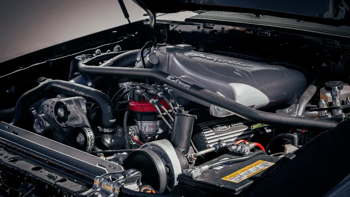
You ride your motorcycle in tough conditions. Heat builds up fast, and you need parts that stand up to the challenge. A silicone radiator hose gives you strong heat resistance, lasting durability, and reliable performance. You can choose custom colors and shapes to match your bike and show your style. The right hose helps your engine stay cool and keeps your ride looking sharp.
Key Takeaways
- Silicone radiator hoses withstand extreme temperatures up to 356°F, ensuring your engine stays cool even in tough conditions.
- These hoses last significantly longer than rubber hoses, with a lifespan of 5 to 15 years, saving you money on replacements.
- Custom-fit silicone hoses improve cooling efficiency and prevent leaks, enhancing your motorcycle's performance and reliability.
- Regular maintenance, including inspections every few months, helps extend the life of your silicone hoses and keeps your cooling system in top shape.
- Investing in high-quality silicone hoses from trusted brands ensures durability and performance, giving you peace of mind on every ride.
Silicone Radiator Hose Features
High Temperature Resistance
You need a radiator hose that can handle extreme heat. Silicone radiator hose stands out because it resists temperatures much higher than standard rubber hoses. You can see the difference in the table below:
| Hose Material |
Max Temperature |
Best For |
Common Uses |
| Silicone |
180°C (356°F) |
Extreme heat, performance, longevity |
Turbo/intercooler, coolant, heater, industrial steam |
| EPDM Rubber |
120°C (248°F) |
Most automotive cooling/heating needs |
Radiator, heater, coolant hoses |
Laboratory tests show that silicone radiator hose can withstand temperatures up to 356°F for long periods. You do not have to worry about softening or bursting. The hose keeps its shape and strength under pressures up to 174 PSI. After 1,000 hours of testing with coolant at high pressure, the hose showed no leaks or cracks. You can trust it to protect your engine from overheating.
RAINBOW’s hoses meet strict quality standards. The company holds ISO 9001 certification and complies with SAE J20 R4 Class A specifications. You get a product that passes tough industry tests.
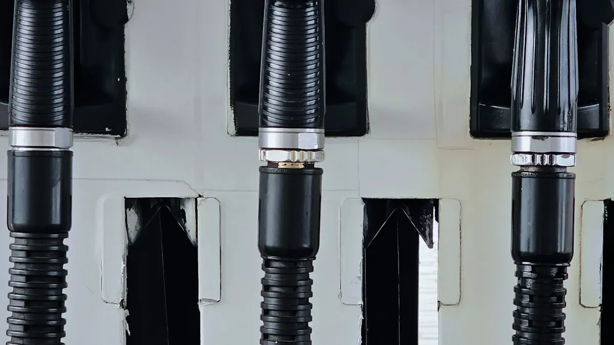
Flexibility & Durability
You want a hose that bends easily and lasts for years. Silicone radiator hose uses 3-ply or 4-ply polyester reinforcement. This design gives you flexibility without kinking or splitting. Flexibility tests prove that the hose can bend over 100 times and still work perfectly.
You can expect a long lifespan. Most silicone radiator hoses last between 5 to 8 years under continuous high-temperature conditions. High-quality hoses, like those from RAINBOW, may last even longer. You save money and avoid frequent replacements.
RAINBOW offers custom fit options. You can choose hoses that match your motorcycle’s unique shape and size. You also get vibrant color choices, such as black, red, or blue. Your bike looks great and performs even better.
Chemical Compatibility
You need a hose that resists chemicals found in motorcycle cooling systems. Silicone radiator hose handles water, air, coolant, and small amounts of oil mist. Premium materials make the hose resistant to heat, pressure, and chemicals. These features help the hose deliver reliable performance.
You do not have to worry about leaks or damage from common fluids. The hose stays strong and keeps your engine safe. RAINBOW’s hoses are not recommended for oil, fuel, or power steering fluid, but they work perfectly for cooling applications.
Benefits for Hot Motorcycles
Preventing Overheating
You want your motorcycle to stay cool, even when you push it hard. A silicone radiator hose helps your engine avoid overheating in extreme conditions. The special silicone material keeps its shape and strength from -60°C to +230°C. It does not deform, even when your cooling system faces high pressure. This means your coolant flows smoothly, and your engine stays at the right temperature.
Here is a table that shows how silicone hoses protect your engine:
| Feature |
Description |
| Extreme Temperature Performance |
Specially formulated silicone withstands continuous temperatures from -60°C to +230°C. Maintains flexibility and integrity in extreme riding conditions. Prevents hose deformation under high-pressure cooling systems. |
| Cooling System Advantages |
Superior heat dissipation properties. Reduced risk of coolant boiling and vapor lock. Maintains optimal engine temperature under heavy load. Prevents coolant loss and overheating issues. |
| Durability & Maintenance |
5x longer service life compared to OEM rubber hoses. Resists ozone cracking and UV degradation. No more periodic hose replacements. Easy to clean and maintain. |
Field tests prove the value of silicone hoses. For example, a 1968 Mustang GT/CS used silicone hoses during racing. The car kept its coolant and held safe temperatures for four hours, even with pressure spikes. Diesel generators with silicone hoses survived continuous exposure to 320°C and short bursts up to 350°C. The hoses did not swell or leak.
Longevity Under Stress
You need parts that last. Silicone radiator hoses resist cracking, swelling, and hardening, even after years of use. They do not break down from ozone, UV light, or chemicals. Riders who switch to silicone hoses often find that these hoses outlast the bike itself. One rider reported that after five years of heavy use, his hoses showed no cracks. In contrast, rubber hoses on his old bike failed every two years.
- Silicone hoses resist thermal degradation and stay flexible over time.
- They last much longer than rubber hoses, which often crack or harden.
- Silicone hoses keep their shape and strength, even in high heat or under heavy engine stress.
- You do not need to replace them as often, which saves you time and money.
In tough tests, silicone hoses handled temperatures from -65°F to 500°F. Rubber hoses softened and cracked, but silicone hoses stayed strong. They passed pressure tests up to 20 bar without bursting. This means you can trust your cooling system, even on long rides or in extreme heat.
Performance Boost
You want your motorcycle to run at its best. Silicone radiator hoses improve coolant flow and help your engine perform better. Their smooth inner surface reduces friction, so coolant moves quickly and evenly. This keeps your engine at the right temperature and protects it from damage.
- Silicone hoses are flexible and durable, which helps your cooling system work efficiently.
- They resist high temperatures, so they do not swell or block coolant flow.
- Premium silicone hoses keep your engine safe by preventing leaks and maintaining steady coolant movement.
When you use a silicone radiator hose, you get better cooling, fewer breakdowns, and more reliable performance. Your engine stays cool, even when you ride hard or in hot weather. You spend less time on repairs and more time enjoying your motorcycle.
Silicone Radiator Hose vs. Other Materials
Silicone vs. Rubber
You want your motorcycle to perform well in every condition. Choosing the right hose makes a big difference. Silicone radiator hose stands out when compared to traditional rubber hoses. Look at the table below to see how these materials differ:
| Property |
Silicone Hose |
EPDM Rubber Hose |
| Max Continuous Temp |
350°F (177°C) |
257°F (125°C) |
| Min Temperature |
-65°F (-54°C) |
-40°F (-40°C) |
| Typical Service Life |
8–15+ years |
3–7 years |
| UV / Ozone Resistance |
Excellent |
Moderate |
| Pressure Resistance |
High |
Moderate |
| Oil / Fuel Resistance |
Poor |
Good |
| Flexibility at Low Temp |
Remains flexible |
Stiffens / can crack |
| Typical Price (per foot) |
$5–$20 |
$1–$6 |
| Color Options |
Wide |
Mostly black |
You see that silicone hoses handle higher temperatures and last longer. They resist UV and ozone damage, so you do not need to worry about cracks or fading. Rubber hoses cost less at first, but you replace them more often. Over five years, silicone hoses save you money because you avoid frequent replacements and emergency repairs.
- Silicone hoses last 10–15 years.
- Rubber hoses need replacement every 3–5 years.
- Fewer replacements mean lower maintenance costs.
- You spend less on materials and labor.
-
Silicone vs. Reinforced Hoses
You may wonder how silicone hoses compare to reinforced hoses made from EPDM rubber. Silicone hoses offer several advantages:
- They withstand temperatures from -50°C to +220°C, while EPDM hoses only handle -40°C to +125°C.
- Silicone resists wear, oil, grease, and chemicals better than EPDM.
- You get excellent resistance to weather and UV light, so your hose stays strong in harsh environments.
- Silicone hoses remain flexible and do not kink or collapse, even when your motorcycle vibrates or moves.
You choose silicone hoses for durability and performance. They keep your cooling system reliable and efficient, even during tough rides. If you want a hose that lasts and looks great, silicone is the best choice.
Choosing Silicone Radiator Hose
Construction Quality
You want a hose that lasts and performs well. Construction quality matters most. Look for hoses with strong reinforcement. Most high-quality hoses use 3-ply or 4-ply layers. These layers help the hose stay flexible and strong under pressure. Polyester is the most common reinforcement. Some hoses use fiberglass or meta-aramid for special needs.
| Fabric Reinforcement |
Characteristics |
| Polyester |
Most common and affordable |
| Fiberglass |
Higher temperature resistance |
| Nomex® |
Specialized applications |
| Meta-Aramid |
High-performance applications |
You should check for ISO 9001 certification and SAE J20 Class A compliance. These standards show that the hose meets strict quality and safety rules. Hoses with these certifications give you peace of mind.
-
Installation & Maintenance
Installation Steps
Installing a silicone radiator hose on your motorcycle helps you get the best cooling performance. You can follow these steps to make sure you do it right:
- Drain the Coolant: Place a drain pan under the radiator. Open the drain valve and let the coolant flow out. Remove the old hose completely. Check that no rubber pieces stay in the radiator necks.
- Inspect the Radiator Necks: Clean the surfaces where the hose connects. Use a clean rag to wipe away dirt or debris. A clean surface prevents leaks.
- Position the Silicone Hose: Slide the new silicone hose onto the radiator neck. Make sure the hose sits evenly and does not twist.
- Install the Clamps: Put stainless steel clamps over the hose ends. Do not tighten them yet.
- Connect the Cylinder Side: Move the hose to the cylinder head port. Gently wiggle the hose if needed to line up the ports.
- Final Clamp Tightening: Once both ends fit well, tighten the clamps. Use a torque wrench if you have one. Aim for 5-7 Nm. The hose should feel snug, not crushed.
- Refill and Bleed: Pour in fresh coolant. Start the engine and let it warm up. Check for leaks while the engine runs.
-
Maintenance Tips
You want your silicone radiator hoses to last as long as possible. Regular checks help you spot problems early and keep your cooling system working well.
- Inspect your hoses every few months for signs of wear, swelling, or cracks.
- Replace silicone coolant hoses every 4 to 6 years, even if they look fine. High heat and pressure can weaken hoses over time.
- Clean the hose surfaces with a damp cloth to remove dirt and oil.
- Check clamps for tightness. Loose clamps can cause leaks.
- Watch for coolant leaks around hose connections after long rides.
You want your motorcycle to stay cool and look great. Silicone radiator hoses give you strong heat resistance, long-lasting durability, and better performance. When you choose certified, custom-fit hoses like those from RAINBOW, you get:
- Heat-resistant fibers that handle high temperatures and pressure
- High-strength silicone that lasts longer than rubber hoses
- Direct-fit designs for better fitment and style
Upgrade your cooling system for more reliability and a bold look on every ride.

FAQ
What makes silicone radiator hoses better than rubber hoses?
You get higher heat resistance and longer lifespan with silicone hoses. They resist cracking and fading from sunlight. Silicone hoses also come in many colors, so you can match your bike’s style.
Can I use silicone radiator hoses for all motorcycle fluids?
You should use silicone hoses for coolant, water, and air. They handle small amounts of oil mist. Do not use them for fuel, oil, or power steering fluid.
How do I know if a silicone hose fits my motorcycle?
Check your motorcycle’s model and measurements. Custom-fit options from brands like RAINBOW let you send drawings or samples. You get a hose that matches your bike perfectly.
How often should I replace silicone radiator hoses?
Inspect your hoses every few months. Replace them every 4 to 6 years, even if they look good. High heat and pressure can weaken hoses over time.
Do silicone radiator hoses improve engine performance?
You get smoother coolant flow and better heat management. This helps your engine stay cool and run more efficiently. Silicone hoses also reduce the risk of overheating.
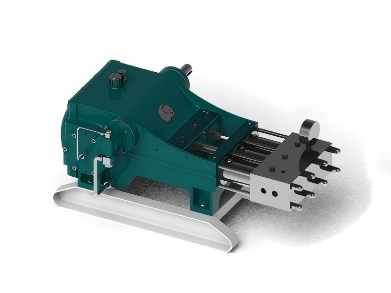
If you want to get more details about us, plz click www.rainbow-manufacturing.com.